KNOWLEDGE / INSIDE MANUFACTURING
One design.
A production plan.
A finished drawing still needs a repeat layout, an order of operations and a shared print-to-cut reference. Follow the decisions between the file and the production run.
Start at prepressPrepress · Process planning · Finishing · Production differences
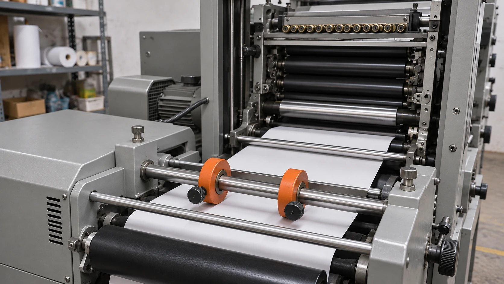
The product drawing is not the press layout.
Prepress connects one finished design with the space and references required by the equipment and later operations.
- Repeat and spacing
- Arrange repeated designs on the usable sheet or web. Leave room for cutting and other process requirements instead of filling every available gap.
- Direction and order
- Decide which edge enters first and how each repeated design is oriented. The print file, cut file and finished-roll requirement should use the same direction reference.
- Registration references
- Keep trim boundaries and equipment registration references separate. Where optical marks are needed, use the workflow and mark format required by that equipment.
Even if the illustration stays the same, a different outer size can change how many units fit, the cutting path and the arrangement of finished pieces. Recheck the layout together with the next operation.
Prepress references and file handover
A practical handover identifies the current artwork, production layout, direction, cutting path and required equipment marks. Imposition examples show how repeated units and printer marks are combined; actual registration marks must follow the machine workflow.
Fiery · Repeat imposition example ↗ · Roland DG · Print/cut workflow ↗
Discuss a design revision →Plan the job around what must be processed.
Design count, quantity, surface operations and final outline affect the preparation and handover between processes.
Swipe horizontally to read all columns.
| Job requirement | Planning decision | Effect on the next step |
|---|---|---|
| Several designs in one order | Separate the quantity and file revision for each design, then review whether they can share a layout and settings. | Keep the printed lanes or sheets and their intended finishing outputs identifiable. |
| A repeat design in a longer run | Review repeat layout, output preparation and production changeovers for the chosen process. | Agree how the repeated output will be divided into finished pieces or rolls. |
| An additional surface operation | Review the trial result and compatibility with printing and subsequent cutting before fixing the sequence. | The surface condition becomes an input to the following operation. |
| Different target and patch outlines | Separate the cut paths, required cut depth and retained liner areas in the finishing plan. | Peeling and material separation depend on this arrangement. |
These are planning questions for a manufacturing job. The equipment, sequence and trial scope are confirmed for the selected material and product.
The next machine needs the same position reference.
A correct-looking print still needs to meet the intended cut path. Registration connects these two operations.
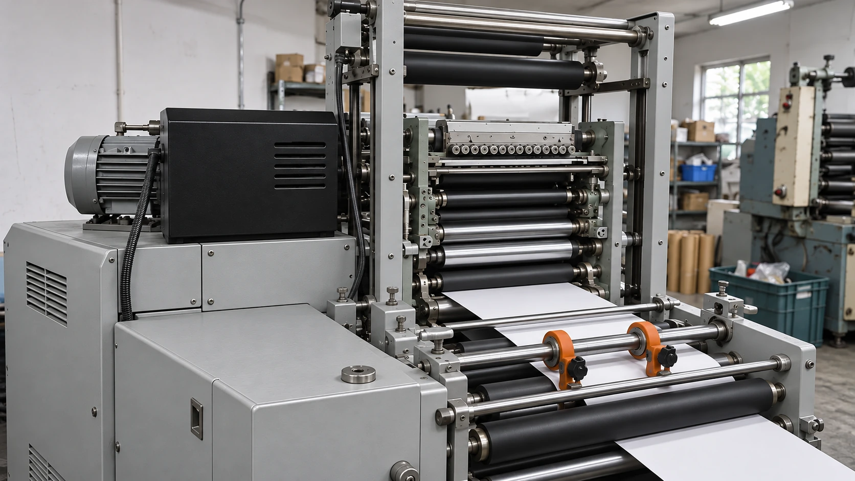
- Before starting
- Match the artwork revision, production layout and cutting file. Check direction and scale before using a position adjustment to compensate for a file mismatch.
- At the first output
- Use a trial output to compare the printed image and intended cut position. A position accepted for printing should still be usable by the next operation.
- Across the run
- If alignment differs, distinguish a similar offset on every repeat from a difference that changes along the feed direction. The pattern helps decide what to review.
Solid rings: printed artwork · Dashed rectangle: intended cut outline
Compare the intended image position with the finished outline.
Record direction and extent, then review the files and registration.
Position diagram, exaggerated for clarity; no acceptance tolerance is implied. Roland DG · Print and cut alignment ↗
An outline, a sheet edge and a roll are three jobs.
Die cutting, sheet separation, slitting and rewinding address different parts of the finished format.
01 / Define the individual outline
The cut path defines a target or repair patch. For peel-off pieces, the cut depth must suit the construction so the face separates while the liner still supports it.
Handover: outline file, cut mode, test-cut result.
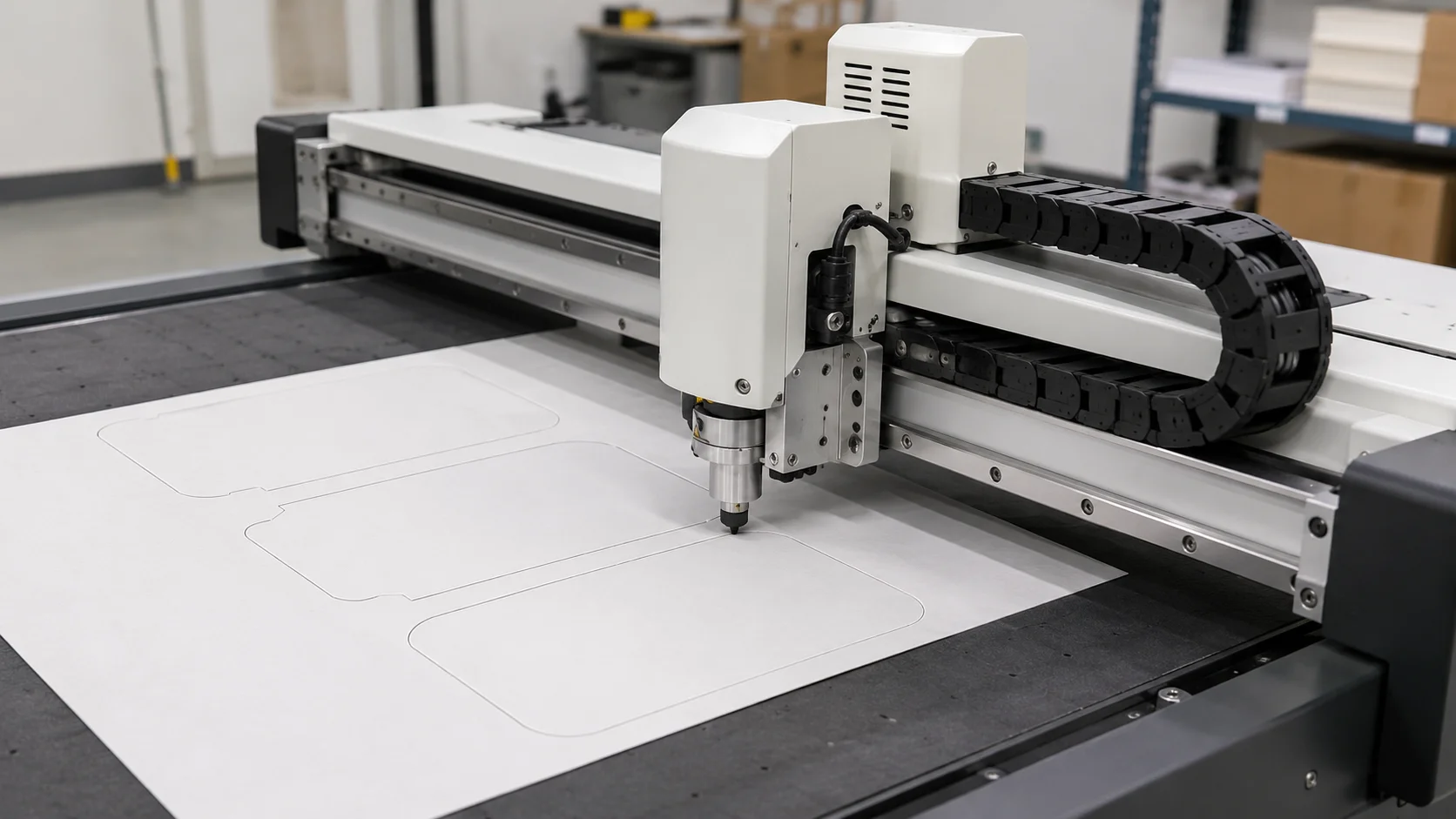
02 / Separate the finished sheet
A sheet or individual piece needs its outside edge separated from the surrounding material. The final outline, remaining mounting border and print position need to agree in the same layout.
Handover: finished outline, alignment reference, sheet arrangement.
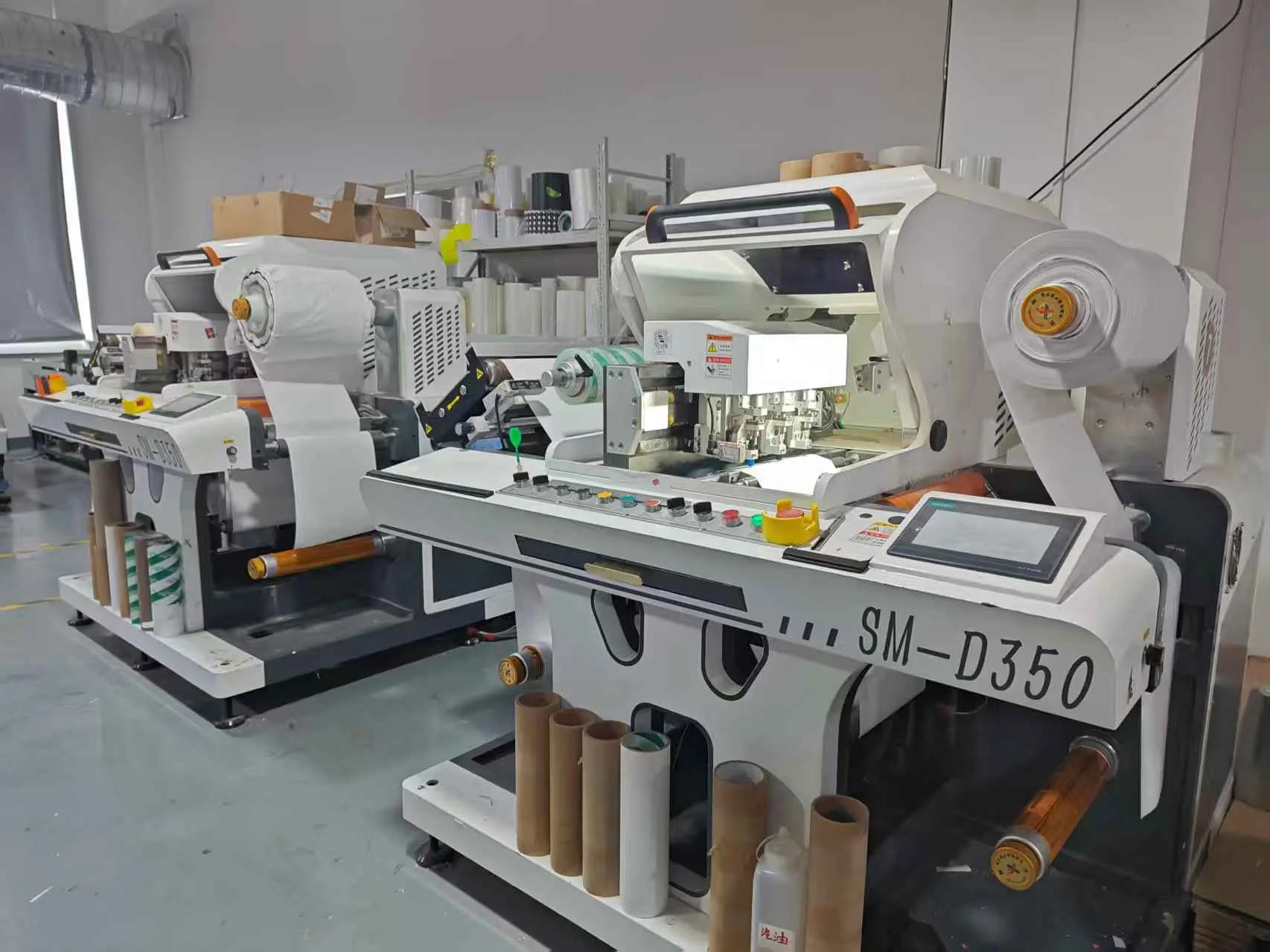
03 / Organize the finished roll
Slitting divides a wider web into narrower lanes. Rewinding organizes material into finished rolls. These decisions concern the web width and roll arrangement, separately from each target’s cut outline.
Handover: lane width, core, winding direction and contents per roll.
Why a test cut comes before settings are fixed
Cutting results depend on the blade, material and machine settings. A setting that separates one stock cleanly may not work the same way on another. Trial cutting is used to check separation and the retained backing before settling on the settings for that job.
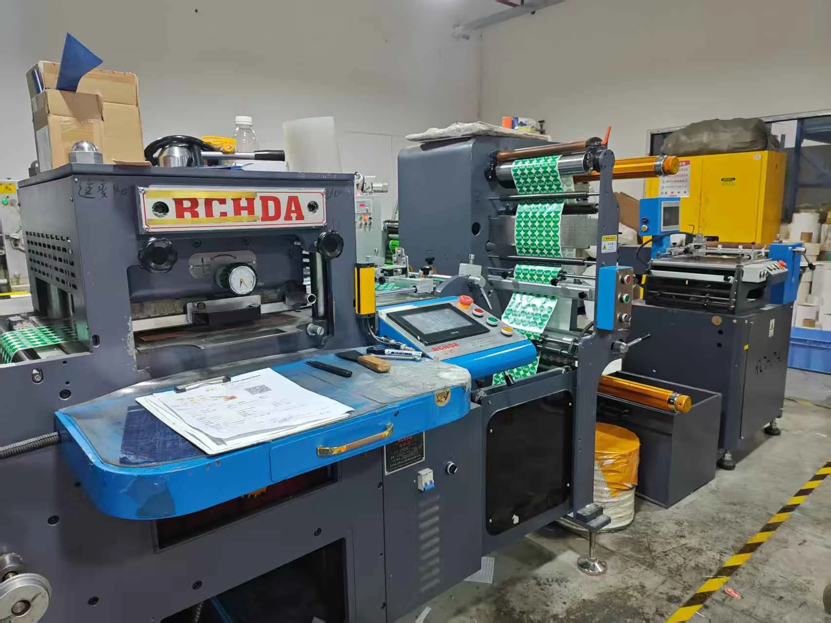
Equipment photographs document the workshop and supplier audit; the operations above explain manufacturing tasks, not a claim that every pictured machine is used for every SKU. See the workshop and equipment records →
A small change can reach more than one operation.
Track what changed in the production inputs, then identify which files, settings and outputs need another review.
Swipe horizontally to read all columns.
| Change | Review before output | Review in finishing |
|---|---|---|
| Logo or wording | Artwork revision and output file; confirm any process-specific preparation that changes. | Check nearby cut paths and retained margins if the new content is close to an edge. |
| Finished size or outline | Repeat layout, orientation and usable area. | Cut path and tooling where applicable; sheet or roll arrangement. |
| Material | Material reference, output compatibility and any trial needed. | Trial-cut settings, separation and handling of the retained backing. |
| Targets per roll | Identify the artwork and individual target specification that remain in use. | Finished-roll arrangement, counting basis and corresponding label information. |
Keep the job reference, artwork and cut-file revisions, material reference, trial result and agreed finished output together. For a repeat run, compare the changed fields before reusing the earlier setup.
Describe the difference before naming the cause.
A location, a direction and a pattern of change are more useful than a single photo labelled “not right”.
The print-to-cut offset is similar on every piece
First compare the artwork and cut-file origins, orientation and registration reference. A repeatable fixed offset and a changing offset are different observations; record the direction and extent before adjusting anything.
The beginning aligns, but later positions move
Compare several positions along the feed direction, including repeat spacing and any change of material position. Mark where the difference begins. Review the feed and registration method for the actual equipment, rather than moving the entire cut file by guesswork.
A sticker will not separate cleanly, or the liner tears
Keep an unpeeled sample and a peeled example. Check the cut line and liner, then review the blade, material and test-cut settings. Equipment guidance treats force, speed and blade offset as material-dependent settings; there is no single setting for every stock.
A repeat order differs from the earlier run
Compare artwork and cut-file revisions, material references and production conditions before naming a cause. A shared product name alone does not establish identical production inputs.
Troubleshooting prompts, not a diagnosis of a specific batch. Cutting parameter reference: Roland DG · Material-dependent cutting conditions ↗